 English
 中文简体
 Español
 عربى


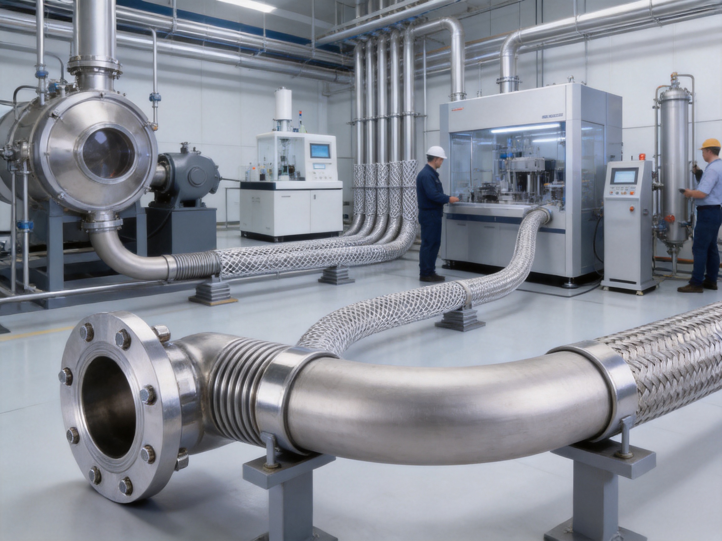
Industrial hose assemblies are critical components in vacuum systems, gas distribution equipment, semiconductor machinery, analytical instruments, laboratory installations, and precision process lines. Although a hose may appear to be a relatively simple connection, its performance directly affects system tightness, operating safety, equipment mobility, vibration isolation, and maintenance cost. A hose that is poorly selected, inadequately formed, or incorrectly connected can introduce leakage, restrict flow, transmit vibration, or fail prematurely under repeated movement.
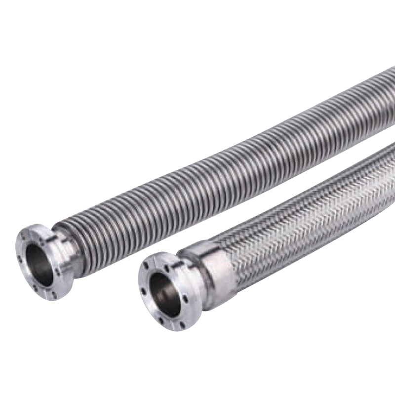
The ConFlat flange type industrial hose is designed for applications that require a dependable stainless-steel connection and a low-leakage flow path. It combines a flexible metal hose body with ConFlat-style flange ends, allowing it to connect with vacuum equipment and other flanged components where clean, reliable sealing is essential. The available construction uses SUS304 or SUS316L for the hose and flange, with an optional stainless-steel mesh sleeve for additional mechanical protection and pressure capability.
This product is suitable for both static and dynamic service. Standard lengths range from 200 to 5,000 millimeters, while customized lengths and larger nominal sizes can also be manufactured. Its specifications cover bore sizes from 20 to 50 millimeters as standard, with DN65 and larger sizes available upon request. Depending on the model and configuration, the hose can operate from vacuum conditions to positive pressure, with a rated static pressure of up to 2.0 MPa and a dynamic pressure rating of up to 1.6 MPa.
This article explains the product’s construction, technical characteristics, manufacturing advantages, application areas, selection factors, installation requirements, and quality considerations. It also discusses why a specialist manufacturer with integrated forming, welding, heat treatment, testing, and custom engineering capabilities can provide advantages over general-purpose hose suppliers.
Content
- 1 1. Product Overview
- 2 2. Key Technical Characteristics
- 3 3. Standard Dimensions and Configuration Options
- 4 4. Advantages Compared with General-Purpose Industrial Hoses
- 5 5. Manufacturing Process and Quality Control
- 6 6. Manufacturing Strengths of the Supplier
- 7 7. Applications
- 8 8. Selection Guide
- 9 9. Installation and Maintenance Recommendations
- 10 10. Troubleshooting Common Problems
- 11 11. Why Integrated Production Matters to Buyers
- 12 12. Recommended Purchasing Information
- 13 13. Frequently Asked Questions
- 13.1 Q1: What is the main purpose of a ConFlat flange type hose?
- 13.2 Q2: Is this hose suitable for vacuum service?
- 13.3 Q3: What is the difference between the non-mesh and mesh versions?
- 13.4 Q4: Which material should be selected, SUS304 or SUS316L?
- 13.5 Q5: What standard sizes are available?
- 13.6 Q6: What standard lengths are available?
- 13.7 Q7: Can the hose be used for dynamic movement?
- 13.8 Q8: Can the hose correct a major pipe misalignment?
- 13.9 Q9: Why is the dynamic pressure rating lower than the static rating?
- 13.10 Q10: What information is needed for a custom quotation?
- 13.11 Q11: How should the hose be maintained?
- 13.12 Q12: Is the product suitable for every gas?
- 14 14. Conclusion
- 15 References
- 16 Product: CONFLAT FLANGE TYPE
1. Product Overview
The ConFlat flange type hose is a flexible metal hose assembly intended for the controlled transfer of gases, air, vacuum environments, and compatible industrial media. Its main body is manufactured from stainless steel, while its end connections are formed with precision flange components. The flange arrangement is intended to create a stable, accurate interface with compatible equipment and piping.
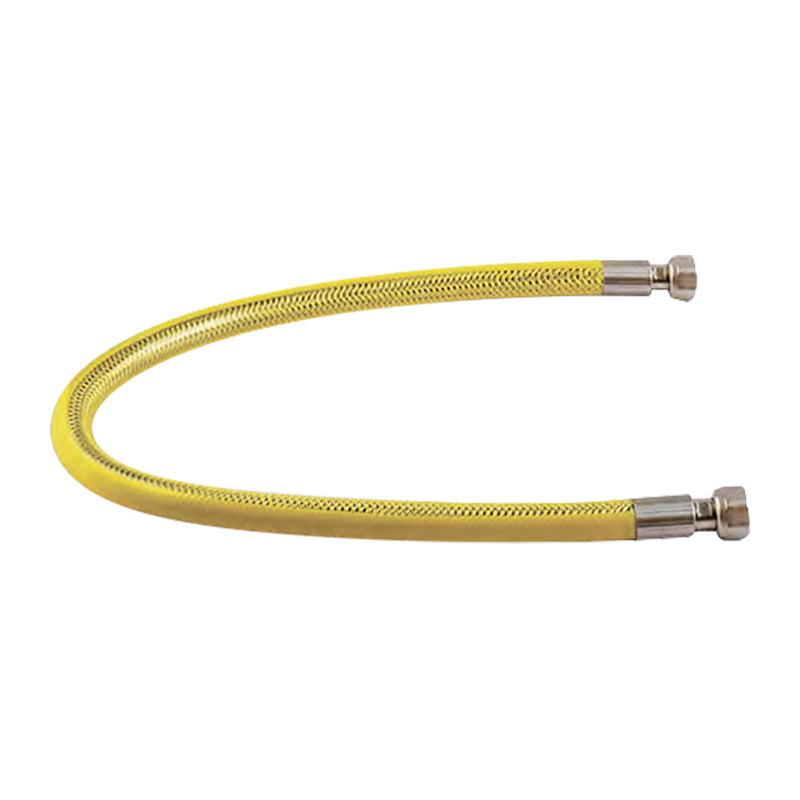
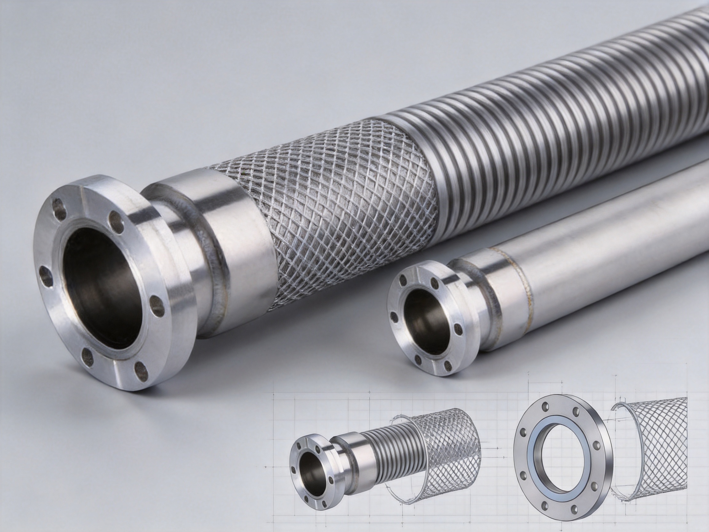
The product is offered in two primary configurations. The first is a non-mesh vacuum hose, which prioritizes flexibility and a compact structure. The second is a hose with a stainless-steel mesh sleeve, which adds reinforcement around the corrugated hose body. The mesh version is particularly useful where the assembly may be exposed to mechanical impact, external abrasion, pressure pulsation, or greater handling loads.
The standard material options include SUS304 and SUS316L. SUS304 is widely used for general industrial service because it combines corrosion resistance, formability, strength, and cost efficiency. SUS316L contains molybdenum and has improved resistance to many corrosive environments, making it preferable for more demanding applications, cleaner process conditions, and systems where reduced carbon content is advantageous for welding and corrosion performance.
The product’s stated allowable leak rate is 1.33 × 10⁻¹⁰ Pa·m3/sec or below. This low leakage specification makes the hose appropriate for vacuum equipment and other systems where loss of pressure, air ingress, or contamination caused by leakage must be minimized.
In addition to the standard catalog dimensions, the manufacturer can produce non-standard lengths and larger nominal diameters. This flexibility is important because actual equipment layouts often require a hose length that is not available from standard inventory. A custom-made assembly can reduce unnecessary bends, adapters, and intermediate joints.
CONFLAT FLANGE TYPE
2. Key Technical Characteristics
2.1 Stainless-Steel Construction
The use of stainless steel throughout the principal hose assembly provides a strong balance between flexibility and durability. Stainless steel resists rust and maintains its mechanical properties across a broad range of industrial environments. It is also suitable for welding, forming, cleaning, and controlled fabrication processes.
The hose body, flange, and mesh sleeve can be manufactured using SUS304 or SUS316L. Matching or carefully selected material combinations help reduce galvanic concerns and simplify material verification. For systems that handle clean gases or operate under vacuum, stainless steel also offers a comparatively low-outgassing and cleanable surface when properly manufactured and prepared.
The choice between SUS304 and SUS316L should be based on the conveyed medium, ambient environment, cleaning method, temperature, expected service life, and customer specifications. General plant air, neutral gases, and many standard industrial services may be suitable for SUS304. More corrosive gases, humid environments, chemical processing areas, and demanding cleanliness requirements may justify SUS316L.
2.2 ConFlat Flange Connection
A ConFlat flange connection is recognized for its use in high-vacuum and precision vacuum systems. The flange provides a controlled connection geometry and can be used with an appropriate gasket and fastening arrangement. Compared with improvised threaded or compression connections, a correctly manufactured flanged assembly can provide better repeatability, easier inspection, and greater compatibility with standardized vacuum equipment.
The flange dimensions in the standard table include the flange outside diameter, bolt-circle-related dimensions, bolt-hole quantity and diameter, and the internal connection diameter. For example, the CF20 model is listed with a flange dimension of 54 millimeters, a K dimension of 41.3 millimeters, and six bolt holes of 6.6 millimeters diameter. Larger models increase the flange and bore dimensions to accommodate higher flow requirements and larger equipment interfaces.
Flange accuracy is essential. If the flange face is not properly formed, aligned, or finished, the assembly may be difficult to install or may fail to achieve the required sealing performance. The flange must remain sufficiently stable during welding and handling so that its sealing surface and bolt-hole pattern remain within the customer’s required tolerances.
2.3 Vacuum and Positive-Pressure Service
The standard working-pressure description identifies service from vacuum to atmospheric pressure, while the dimensional table provides pressure ratings for static and dynamic conditions. The listed static pressure range is -0.1 to 2.0 MPa, and the listed dynamic range is -0.1 to 1.6 MPa. These values should be interpreted together with the operating temperature, hose movement, media compatibility, installation method, and actual customer design conditions.
Static service generally creates less mechanical fatigue because the hose remains in a fixed position. Dynamic service introduces repeated bending, vibration, or movement, which places greater stress on the corrugations and end connections. For this reason, the dynamic pressure rating is lower than the static rating in the standard specification.
Users should not select a hose solely by comparing the maximum pressure number. A proper selection also considers pressure pulsation, vacuum cycling, movement frequency, bend radius, mounting direction, thermal expansion, external loads, and the possibility of sudden pressure changes. When a system operates near the limits of the standard range, technical confirmation should be obtained before production.
2.4 Low Leakage Performance
The allowable leak rate of 1.33 × 10⁻¹⁰ Pa·m3/sec or below is a significant product characteristic. In vacuum equipment, even a small leak can affect pump-down time, process stability, gas purity, measurement accuracy, and operating cost. Leakage can originate from the hose wall, weld areas, flange connections, gasket interfaces, or damage caused during installation.
Achieving low leakage requires more than using stainless steel. It depends on suitable material preparation, controlled forming, consistent welding, correct flange alignment, appropriate cleaning, and reliable inspection. The entire assembly must be treated as a pressure boundary. A high-quality flange attached to a poorly formed hose does not provide a dependable system connection, and a well-formed hose can still fail if the end weld is incomplete or contaminated.
3. Standard Dimensions and Configuration Options
The following table summarizes the standard dimensions and performance information supplied for the ConFlat flange type hose. Dimensions are presented in millimeters unless otherwise indicated. The term “no internet” in the source data appears to refer to the non-mesh or unreinforced configuration, while “with a net” refers to the mesh-reinforced configuration.
| Bore | Model | D | K | Bolt Holes | D1 | Length | Static Pressure | Dynamic Pressure | Static Minimum Bend Radius | Dynamic Minimum Bend Radius |
|---|---|---|---|---|---|---|---|---|---|---|
| 20 | CF20 | 54 | 41.3 | 6-Ø6.6 | 28.2 | 200–5000 | -0.1 to 2.0 MPa | -0.1 to 1.6 MPa | 160 | 360 |
| 25 | CF25 | 60 | 47 | 6-Ø6.6 | 34 | 200–5000 | -0.1 to 2.0 MPa | -0.1 to 1.6 MPa | 175 | 400 |
| 32 | CF32 | 70 | 54 | 6-Ø6.6 | 43 | 200–5000 | -0.1 to 2.0 MPa | -0.1 to 1.6 MPa | 225 | 510 |
| 40 | CF40 | 70 | 58.7 | 6-Ø6.6 | 53 | 200–5000 | -0.1 to 2.0 MPa | -0.1 to 1.6 MPa | 280 | 640 |
| 50 | CF50 | 86 | 72.4 | 8-Ø8.4 | 64 | 200–5000 | -0.1 to 2.0 MPa | -0.1 to 1.6 MPa | 350 | 800 |
The length range of 200 to 5,000 millimeters provides flexibility for equipment connections, vibration isolation, offset compensation, and routing around obstacles. However, length should not be increased merely to create additional flexibility. Excessive length can increase pressure drop, occupy unnecessary space, and create unsupported loops that may be exposed to mechanical loads.
The minimum bend radius is a key design value. The static and dynamic figures are different because repeated movement requires a larger radius to reduce fatigue. A hose that is acceptable in a stationary installation may fail prematurely if it is later used as a moving connection without recalculating the bend radius and movement pattern.
4. Advantages Compared with General-Purpose Industrial Hoses
4.1 Better Suitability for Vacuum Equipment
Many general-purpose hoses are designed primarily for water, air, hydraulic oil, or low-pressure industrial transfer. They may not provide the flange accuracy, leakage performance, material cleanliness, or structural stability required in vacuum equipment. The ConFlat flange type is developed around a flanged metal connection and a low-leakage requirement, making it more appropriate for systems where vacuum integrity is a primary design objective.
Rubber and polymer hoses can provide excellent flexibility, but they may present issues involving permeation, outgassing, aging, chemical compatibility, static charge, and temperature limitations. A stainless-steel hose can offer a more stable solution in applications where these factors are important. The final suitability still depends on the exact media and process conditions, but the metal construction provides a strong foundation for demanding service.
4.2 Stronger Resistance to External Conditions
Stainless steel generally performs better than ordinary elastomeric materials in areas exposed to heat, sparks, oil mist, ultraviolet radiation, abrasion, and industrial cleaning. A mesh sleeve further protects the corrugated body against external contact and helps distribute mechanical loads across the assembly.
This advantage is valuable in manufacturing plants, energy equipment, gas cabinets, vacuum chambers, laboratory systems, and process skids where hoses may be routed through crowded spaces. The reinforced design can reduce the risk of damage during installation and maintenance, provided that the hose is still installed without sharp bends or unsupported weight.
4.3 Controlled Flexibility and Vibration Isolation
A rigid pipe provides excellent dimensional stability but cannot easily absorb equipment vibration, thermal movement, or installation misalignment. A flexible metal hose provides controlled movement between connected components. It can reduce the transfer of vibration from pumps, compressors, valves, and rotating equipment into sensitive instruments or rigid pipework.
The hose also helps compensate for small differences in alignment. This does not mean that it should be used to correct major installation errors. Excessive lateral offset or axial compression can concentrate stress at the corrugations and end connections. Nevertheless, within its specified movement limits, the flexible assembly can simplify equipment layout and reduce the need for complex pipe supports.
4.4 Availability of Unreinforced and Mesh-Reinforced Versions
Different applications require different balances between flexibility, weight, protection, and pressure capability. The non-mesh configuration is useful when low weight and bending flexibility are important. The mesh configuration is appropriate when the assembly requires additional reinforcement or greater resistance to external mechanical loads.
Offering both configurations allows the user to avoid over-specifying every application. A lightweight hose may be more convenient for a laboratory instrument, while a mesh-covered assembly may be preferred near industrial machinery or in a plant environment. Product selection can therefore be matched to actual operating conditions rather than relying on one universal construction.
4.5 Custom Lengths and Larger Sizes
Standardized products are useful for routine purchasing, but industrial systems often need special dimensions. The ability to manufacture lengths not shown in the standard table can reduce the number of joints and adapters. The ability to manufacture DN65 and larger sizes supports applications with higher flow requirements or larger vacuum chamber ports.
Custom production can also accommodate special flange combinations, material requirements, end configurations, and project-specific dimensional controls, subject to technical review. A manufacturer that can manage these requirements internally can reduce communication gaps between design, production, and inspection teams.
5. Manufacturing Process and Quality Control
5.1 Material Selection and Traceability
Manufacturing begins with the selection of stainless-steel strip, tube, flange stock, welding consumables, and mesh materials. Material grades should be confirmed against the purchase specification. For critical applications, material certificates and batch traceability help establish a documented link between raw material and finished assembly.
SUS304 and SUS316L should not be treated as interchangeable in every environment. The manufacturer must verify that the selected grade matches the customer’s corrosion, cleanliness, temperature, and welding requirements. Proper storage is also important. Stainless-steel components should be protected from contamination by carbon-steel dust, oil, moisture, and unsuitable handling tools.
5.2 Corrugation and Forming
The flexible hose body is produced through a controlled forming process that creates a series of corrugations. These corrugations allow the hose to bend while maintaining a continuous metal pressure boundary. The geometry of the corrugation affects flexibility, pressure resistance, fatigue life, flow characteristics, and minimum bend radius.
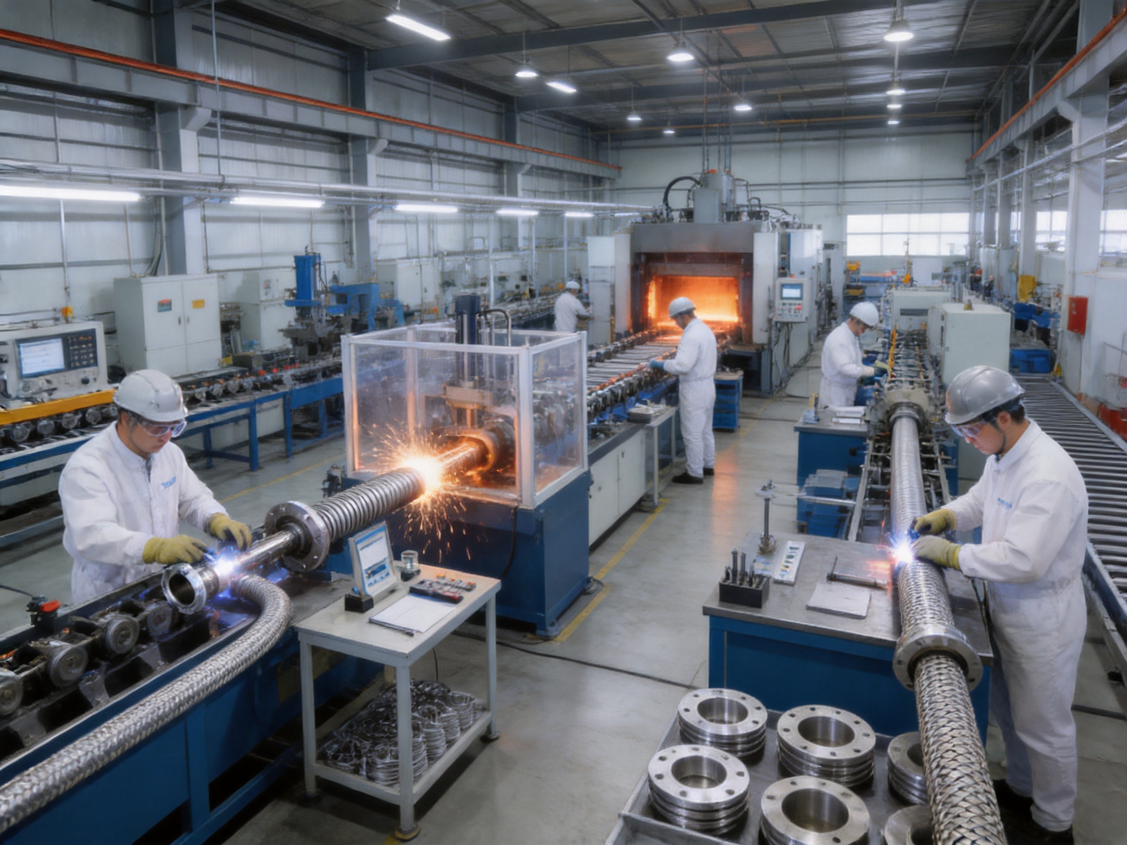
Consistent forming requires stable equipment, suitable tooling, accurate material thickness, and process monitoring. Uneven corrugation depth or spacing can create localized stress and reduce fatigue life. A specialist manufacturer with dedicated forming production lines can establish repeatable process parameters and inspect the formed body before it proceeds to final assembly.
5.3 Welding and End Assembly
The end connection is one of the most important areas of a metal hose assembly. The hose body must be connected to the flange without compromising the corrugation, distorting the flange face, or creating incomplete welds. Welding procedures should control heat input, joint preparation, shielding gas, electrode or filler selection, and post-weld cleaning.
Welding of SUS316L requires particular attention to cleanliness and heat control. Excessive heat can produce distortion or undesirable metallurgical effects, while inadequate shielding can affect the weld surface. Correct fixturing helps maintain flange alignment during the welding process.
After welding, the assembly may undergo visual inspection, dimensional inspection, leak testing, and other examinations appropriate to the customer’s specification. The flange face should be checked for damage, contamination, warping, and bolt-hole accuracy. The hose should be inspected for dents, cracks, abnormal corrugations, and surface defects.
5.4 Mesh Sleeve Installation
For reinforced versions, the stainless-steel mesh sleeve is installed over the hose body and secured at the appropriate end areas. The mesh must fit closely enough to provide support without restricting the hose’s intended movement. It should not contain sharp protrusions, broken wires, loose sections, or areas that could rub against adjacent equipment.
A properly installed mesh sleeve distributes external loads and helps protect the corrugated hose from impact. It does not eliminate the need to respect the minimum bend radius. Bending the assembly more tightly than specified can still fatigue the inner hose, even if the outer mesh appears intact.
5.5 Heat Treatment and Cleaning
Depending on the material, forming method, welding process, and customer requirements, heat treatment may be used to improve material condition or relieve manufacturing stresses. Cleaning and surface treatment are also important for vacuum and gas-service products. Residual oil, particles, oxide, and welding residue can contaminate the connected system.
A manufacturer equipped with uninterrupted solid-melting hydrogen furnace production lines and related process capabilities can support controlled stainless-steel treatment and production requirements. The exact process used for a particular hose should be confirmed with the technical department because treatment requirements depend on material, geometry, cleanliness level, and application.
5.6 Leak Testing and Inspection
Leak testing verifies the integrity of the completed pressure boundary. Testing methods may include pressure decay, helium leak testing, vacuum testing, or other procedures specified by the customer. The required method should match the stated allowable leak rate and the intended application.
Flow tightness testers and metal material analysis equipment provide additional tools for quality control. Direct-reading spectrometers can help verify material composition, while tightness testing helps identify leaks that cannot be detected through visual inspection alone. Dimensional inspection confirms that the final assembly corresponds to the requested bore, flange pattern, length, and end configuration.
Quality control should cover the entire production chain rather than relying only on final inspection. Incoming material checks, in-process forming checks, weld monitoring, cleaning controls, final dimensional measurement, and leak testing together create a more reliable quality system.
6. Manufacturing Strengths of the Supplier
The supplier is an energy equipment manufacturer and processor with capabilities covering metal hoses, natural gas pipelines, plumbing fittings, sanitary ware, valves, plastic products, and hardware. This product range provides experience with both flexible metal components and broader fluid-handling systems.
The company operates a production facility in Yuyao, Zhejiang, with a reported factory building area of approximately 30,000 square meters. Its manufacturing resources include 30 welding and forming production lines, two uninterrupted solid-melting hydrogen furnace production lines, and testing equipment for metal material analysis and flow tightness. These resources indicate an integrated production structure rather than a business limited to trading finished products.
An integrated factory can provide several practical benefits. Production schedules can be coordinated across forming, welding, heat treatment, assembly, and testing. Engineering staff can review non-standard dimensions directly with manufacturing personnel. Quality feedback can be returned to the relevant process more quickly. This may help reduce lead time and improve consistency for custom hose assemblies.
The company reports implementation of the ISO9000:2008 quality management system, a special equipment manufacturing license for pressure pipelines in the People’s Republic of China, and EU CE certification testing reports. These qualifications and reports can support customer due diligence, although buyers should always request current certificates, applicable scopes, and product-specific documentation for the project under consideration.
Membership in the China Urban Gas Association also reflects involvement in the gas equipment field. Experience with natural gas pipelines, fittings, valves, and related equipment can be valuable when producing hoses for gas transfer and energy infrastructure. Knowledge of complete piping systems helps the manufacturer consider not only the hose body but also connection geometry, pressure behavior, installation constraints, and service conditions.
The company also emphasizes research, development, design, production, and pre-sales and after-sales service. For industrial hose projects, technical service is important because a correct product specification often requires discussion of pressure, movement, media, flange type, length, material, installation direction, and testing. A supplier that can provide engineering communication before production is better positioned to prevent avoidable selection errors.
7. Applications
7.1 Vacuum Equipment and Chambers
The ConFlat flange type is suitable for vacuum equipment where low leakage and clean metallic connections are required. Potential applications include vacuum chambers, coating equipment, analytical instruments, vacuum furnaces, research systems, and laboratory equipment.
In these applications, the hose may connect a vacuum pump, chamber, valve, sensor, or moving equipment section. The flexible assembly can help reduce vibration transmission and simplify access during maintenance. The user should ensure that the hose material, internal cleanliness, flange size, gasket, and leak test method are compatible with the vacuum level and process gas.
7.2 Gas Equipment and Energy Systems
Metal hose assemblies are commonly used in gas equipment where controlled flexibility and strong connections are required. Applications may include gas manifolds, pressure regulation equipment, gas supply skids, burner systems, and industrial energy equipment.
For combustible, toxic, or chemically active gases, the complete installation must be designed according to applicable codes and safety procedures. The hose must be compatible with the gas, pressure, temperature, and environmental conditions. It should also be protected from impact, excessive vibration, and unauthorized movement.
7.3 Industrial Machinery
Industrial machinery often contains pumps, compressors, motors, valves, actuators, and moving frames. A flexible hose can absorb limited equipment movement and reduce stress on rigid pipework. Mesh-reinforced models may be suitable in areas where the hose is exposed to handling or external contact.
The hose should not be used as a substitute for pipe supports. Its end connections must not carry the weight of adjacent pipework or equipment. Proper supports and guides help ensure that the hose moves in the intended direction and that bending is distributed along the flexible section.
7.4 Laboratory and Analytical Systems
Laboratory instruments often require compact, clean, and reliable connections. The stainless-steel construction can be advantageous where permeation, contamination, or material aging would be undesirable. The CF20, CF25, and CF32 sizes may be appropriate for many smaller vacuum or analytical equipment interfaces, subject to instrument specifications.
Laboratory applications may also involve frequent equipment rearrangement. In such cases, the hose length and bend radius should be selected to permit access without causing repeated over-bending. If the assembly is disconnected regularly, the flange gasket and fastening procedure should be reviewed to ensure consistent sealing.
7.5 Semiconductor and Precision Manufacturing Equipment
Precision manufacturing equipment places strong demands on cleanliness, leakage control, vibration isolation, and dimensional consistency. A stainless-steel flanged hose can support these requirements when it is manufactured, cleaned, packaged, and tested according to the required cleanliness level.
Before use in a sensitive process, the customer should specify acceptable surface condition, cleaning method, packaging requirements, particle control, leak test criteria, and material restrictions. Standard industrial cleaning may not be sufficient for every high-cleanliness application.
8. Selection Guide
8.1 Select the Nominal Bore
The bore should be selected according to the required flow rate, allowable pressure drop, connection size, and system geometry. A larger bore can reduce flow resistance but may increase assembly size, weight, and cost. A smaller bore may be compact but can restrict flow or increase gas velocity.
The hose should not be selected solely by matching the outside diameter. The internal bore and the actual mating flange dimensions must be verified. If the equipment uses a non-standard interface, the manufacturer should review a drawing or sample flange before production.
8.2 Select SUS304 or SUS316L
SUS304 is often suitable for general industrial environments and neutral media. SUS316L is generally preferred when the environment contains chlorides, certain chemicals, moisture, or more demanding cleaning conditions. It may also be selected when the customer’s vacuum or process standard specifies low-carbon austenitic stainless steel.
Material selection should include the flange and mesh sleeve, not only the corrugated hose. Mixed materials may be acceptable in some applications, but the customer should understand their corrosion and thermal behavior.
8.3 Select Mesh or Non-Mesh Construction
Select the non-mesh configuration when the hose is protected, weight is important, and maximum flexibility is desired. Select the mesh version when the hose may be exposed to external abrasion, impact, pressure pulsation, or additional mechanical loads.
The mesh sleeve should not be regarded as a guarantee against misuse. It protects the hose from certain external hazards but does not permit sharp kinks, twisting, axial compression, or unsupported installation.
8.4 Determine the Required Length
The required length should be measured after considering the natural routing path, the required bend radius, flange orientation, and movement direction. A hose should not be stretched to fit or compressed into a space smaller than its design length.
For dynamic service, the length must allow the hose to move gradually rather than bend at one concentrated point. A longer hose is not always better; the design should provide enough length for the planned movement while avoiding loops that can become snagging or load points.
8.5 Confirm Pressure and Movement
Provide the manufacturer with the normal pressure, maximum pressure, vacuum level, pressure cycles, temperature, movement frequency, movement amplitude, and expected service life. These details allow the supplier to distinguish between static and dynamic use and to assess whether the standard pressure and bend-radius values are suitable.
If the application includes rapid pressure pulses, pump vibration, thermal cycling, or continuous movement, these conditions should be stated explicitly. A hose that is suitable for occasional adjustment may not be suitable for continuous robotic movement.
9. Installation and Maintenance Recommendations
Inspect the hose before installation. Confirm the model, bore, length, material, flange pattern, and visible condition. Check that the flange face is clean and undamaged. Remove protective packaging only when the assembly is ready to be installed.
Keep the hose aligned with the connected equipment. Avoid twisting the hose during bolt tightening. Twisting creates torsional stress that may be transferred to the corrugations and welds. If the hose has a prescribed movement direction, install it so that movement occurs in the intended plane.
Do not exceed the minimum bend radius. The dynamic minimum bend radius should be used when the hose moves during operation. The static value should only be used for a hose that remains stationary after installation. Bending should be distributed over the flexible length instead of being concentrated at the flange.
Provide independent supports for adjacent pipes and equipment. The hose should not carry the dead weight of a pipe, valve, pump, or instrument. Supports should also prevent the assembly from rubbing against sharp edges or hot surfaces.
Use the correct gasket, bolts, washers, torque sequence, and tightening procedure for the selected flange connection. Fasteners should be tightened evenly to avoid flange distortion. Over-tightening can damage the gasket or flange, while under-tightening can cause leakage.
After installation, conduct a suitable leak test before placing the system into service. For vacuum applications, verify that the system reaches the expected pressure within the planned pump-down time. For positive-pressure service, conduct a pressure test according to the applicable safety procedure and never exceed the approved test limits of the complete system.
During maintenance, inspect the hose for dents, abrasion, discoloration, corrosion, broken mesh wires, deformed flanges, and evidence of repeated over-bending. If the hose has been exposed to an abnormal pressure event, fire, chemical attack, or severe mechanical impact, it should be evaluated before reuse.
10. Troubleshooting Common Problems
10.1 Leakage at the Flange
Leakage at the flange may result from a damaged gasket, contaminated sealing surface, uneven bolt tightening, flange misalignment, or a distorted flange. Remove the assembly from service safely, inspect the sealing area, replace damaged sealing components, and reinstall according to the approved procedure.
If leakage continues after the gasket and fastening method have been checked, the flange face or weld area may require inspection. A professional leak test should be used rather than relying solely on audible sound or visible signs.
10.2 Leakage from the Hose Body
Leakage from the corrugated section may be caused by fatigue, corrosion, excessive bending, external impact, or a manufacturing defect. A damaged metal hose should generally be replaced rather than repaired with an external patch. Any repair must be approved by the responsible engineering authority because the hose is part of the pressure boundary.
10.3 Premature Fatigue
Premature fatigue often occurs when the hose is bent below its recommended radius, twisted during installation, used in continuous movement without a dynamic design review, or exposed to vibration beyond the intended service conditions. Recheck the movement path and install guides or supports where necessary.
10.4 Unexpected Pressure Drop
Pressure drop may be caused by selecting a bore that is too small, installing an excessively long hose, creating a sharp bend, allowing the hose to collapse, or introducing contamination into the flow path. Review the flow requirement and compare the actual installation with the original design.
10.5 Corrosion or Surface Discoloration
Surface discoloration may indicate contamination, exposure to unsuitable chemicals, high-temperature oxidation, or inadequate cleaning after welding. The correct response depends on the environment and severity. Material selection, cleaning procedures, and exposure conditions should be reviewed before replacing the assembly.
11. Why Integrated Production Matters to Buyers
Purchasing a metal hose is not simply a matter of buying a flexible tube. The customer is purchasing a pressure-containing assembly with a specific interface, material, length, leakage requirement, and expected service life. The quality of each manufacturing step influences the final result.
An integrated supplier can coordinate material purchasing, forming, welding, furnace processing, mesh installation, dimensional inspection, and leak testing. This can be especially valuable for custom orders because the same organization manages the technical interpretation and production execution.
In-house testing can also shorten the feedback loop. If a flange dimension, weld appearance, or leak result does not meet the specification, the issue can be investigated within the production system. This is generally more efficient than sending components between unrelated subcontractors.
Manufacturing scale is another consideration. Multiple welding and forming lines can support regular production volumes and provide greater scheduling flexibility. At the same time, a strong engineering team is needed to ensure that customization does not compromise standardization, traceability, or inspection.
The supplier’s broader experience with gas pipelines, plumbing fittings, valves, sanitary products, and energy equipment may also help customers who require more than a single hose. For projects involving several pipe components, a supplier with a broad product range can provide more consistent technical communication and coordinated delivery.
12. Recommended Purchasing Information
When requesting a quotation, customers should provide the required bore or nominal size, flange type, flange dimensions, material grade, hose length, mesh requirement, medium, operating pressure, vacuum level, temperature, movement type, minimum bend radius, and required leak rate.
It is also useful to provide a drawing, photographs of the equipment interface, or the part number of the mating component. These references reduce the risk of selecting a flange that appears similar but is not dimensionally compatible.
For projects with regulatory or quality requirements, the quotation request should identify the need for material certificates, inspection reports, leak test records, cleaning certificates, certificates of conformity, packaging specifications, and traceability documentation.
Buyers should ask whether the quoted pressure rating applies to static or dynamic operation, whether the length is measured flange face to flange face, how the bend radius is defined, and whether the rating changes with temperature or media. Clear answers to these questions help prevent misunderstandings after delivery.
13. Frequently Asked Questions
Q1: What is the main purpose of a ConFlat flange type hose?
The main purpose is to provide a flexible, low-leakage connection between compatible vacuum or industrial equipment. It can absorb limited vibration and movement while maintaining a stainless-steel flanged connection.
Q2: Is this hose suitable for vacuum service?
Yes. The product is designed for service from vacuum to atmospheric pressure and has a stated allowable leak rate of 1.33 × 10⁻¹⁰ Pa·m3/sec or below. The actual suitability depends on the required vacuum level, cleanliness, temperature, media, flange gasket, and test procedure.
Q3: What is the difference between the non-mesh and mesh versions?
The non-mesh version has a simpler construction and emphasizes flexibility and lower weight. The mesh version adds a stainless-steel protective sleeve that improves external reinforcement and resistance to handling loads. Both versions must be installed within the applicable bend-radius and movement limits.
Q4: Which material should be selected, SUS304 or SUS316L?
SUS304 is commonly used for general industrial service. SUS316L is preferred for more corrosive or cleanliness-sensitive environments and applications requiring a low-carbon stainless-steel grade. The selection should be based on the medium, environment, temperature, cleaning method, and customer standards.
Q5: What standard sizes are available?
The standard sizes listed are bore 20, 25, 32, 40, and 50 millimeters, corresponding to models CF20, CF25, CF32, CF40, and CF50. DN65 and larger sizes can also be manufactured according to project requirements.
Q6: What standard lengths are available?
The standard length range is 200 to 5,000 millimeters. The manufacturer can produce lengths that are not shown in the standard table after confirming the required dimensions and application conditions.
Q7: Can the hose be used for dynamic movement?
Yes, the specification includes dynamic pressure ratings and dynamic minimum bend-radius values. However, the movement frequency, amplitude, direction, cycle count, pressure, temperature, and installation support should be reviewed before continuous dynamic use.
Q8: Can the hose correct a major pipe misalignment?
No. A flexible hose can accommodate limited alignment variation, but it should not be used to compensate for major errors in pipe or equipment positioning. Excessive offset can overload the corrugations and end connections.
Q9: Why is the dynamic pressure rating lower than the static rating?
Repeated movement creates fatigue stress in the corrugated hose and end connection. Reducing the pressure rating during movement provides a safer operating margin because pressure and flexing act together on the assembly.
Q10: What information is needed for a custom quotation?
Provide the bore, flange type and dimensions, material, length, mesh requirement, medium, pressure, vacuum level, temperature, movement conditions, bend radius, leakage requirement, and any required certificates or inspections. A drawing or photograph of the mating equipment is also helpful.
Q11: How should the hose be maintained?
Inspect it periodically for leakage, corrosion, dents, abrasion, broken mesh wires, flange damage, and abnormal deformation. Confirm that supports remain secure and that the hose has not been twisted or forced below its minimum bend radius.
Q12: Is the product suitable for every gas?
No hose should be assumed to be compatible with every gas. The gas composition, pressure, temperature, moisture, corrosiveness, flammability, toxicity, and cleanliness requirements must be evaluated before selection. Technical confirmation is recommended for hazardous or highly reactive media.
14. Conclusion
The ConFlat flange type industrial hose is a specialized stainless-steel assembly for vacuum equipment, gas systems, industrial machinery, laboratory installations, and other applications requiring a flexible and dependable flanged connection. Its principal advantages include stainless-steel construction, low allowable leakage, standard ConFlat-style dimensions, static and dynamic pressure capability, optional mesh reinforcement, and availability in custom lengths and larger sizes.
Compared with general-purpose polymer or low-pressure hoses, the product offers a stronger combination of vacuum suitability, corrosion resistance, mechanical stability, cleanable construction, and connection repeatability. Its performance depends not only on the listed specifications but also on correct material selection, flange compatibility, installation, support, bend radius, and operating conditions.
The supplier’s integrated resources, including welding and forming production lines, furnace processing capability, metal analysis equipment, leak-tightness testing, quality management practices, pressure-pipeline manufacturing qualifications, and experience with gas and energy equipment, provide a strong foundation for both standard and custom production.
For the best result, customers should treat the hose as an engineered pressure component rather than a simple accessory. Providing complete technical information before ordering allows the manufacturer to recommend the proper bore, material, mesh configuration, length, pressure rating, and inspection requirements. When correctly selected and installed, the ConFlat flange type hose can contribute to safer operation, improved vacuum integrity, reduced vibration transmission, and longer service life throughout the connected system.
References
1. Product technical specification for ConFlat flange type industrial hoses, including material, pressure, leakage, dimensional, and bend-radius data.
2. Stainless-steel material selection principles for industrial piping, flexible hose, and vacuum equipment.
3. General engineering practices for corrugated metal hose installation, support, movement, and minimum bend radius.
4. Quality management principles for welded pressure-containing assemblies and industrial component manufacturing.
5. General vacuum engineering guidance for flange connections, leak testing, cleanliness, and system integrity.
6. Manufacturer information concerning metal hose production, gas pipeline equipment, welding and forming capacity, furnace processing, testing equipment, and quality credentials.